
IEEE has specified a class (Class) of a PoE system ranging from class 0 to class 8 to enable PoE management in order to meet these different needs. PoE supports classes 0 and above for PoE Type 1 and Type 2. Type 3 will support Class 5 (45W) and Class 6 (60W) up to Class 4, whereas Type 4 will support Class 7 (75W) and Class 8 (100W) (90W). On the same PoE switch or power supply, you can have up to eight different classes of POE checker. So if one of these devices isn’t receiving the current it should, it’s a problem. You must resolve these PoE system issues.
Is your PoE not working?
There are numerous reasons why PoE devices may not function properly. Whether it is a connection problem that is frequently caused by an inappropriate connection such as a broken line, a short circuit, or a wrong pair of wires, including cable damage across the link. These issues, in addition to impeding information transmission. It also deactivates the PoE power source. Furthermore, the extra heat increases intra-line signal loss. Another problem could be an ineffective DC resistance imbalance. Alternatively, non-IEEE PoE compliant devices can be used. Typically, even if the calibration link is passed to assure connection continuity, the PoE compatible device does not receive adequate current. The power supply unit (PSE) that is in use is frequently the source of the problem.
PoE-capable switches distribute PoE power to each port in accordance with the needs of the attached devices. This allocation enables the switch to provide more efficient power output. A typical 24-port PoE switch, for example, has a total power limit of 740W, allowing for an average of up to 30W per port (Type 2) However, having different types of PoE devices connected to them on the network means that not every device will use the whole 30 watts of power from the switch. With this allocation technique, you may have a VoIP phone that only needs 7 watts of PoE power from one switch port and security cameras that only need 15.4 watts of power from the other. This reduces the power of each PoE port. This allows the remaining power to be added to the port to which the device is connected, requiring more power than the basic rule requires. The PoE power output of the PSE-side devices must be equal to or greater than the class of connected devices in order for the connected devices to receive an adequate electrical power level to function. This means that for any device that is linked to the same PSE device. The total power used by all devices cannot exceed the PSE’s overall power output.
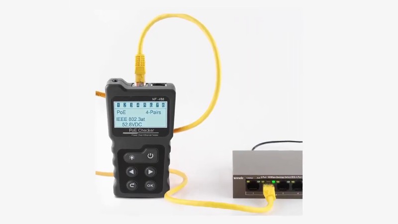
How can you determine the PoE value on a switch port?
Network switches use the standard Link Level Discovery Protocol (LLDP) or the Cisco Device Discovery Protocol (CDP) to discover connected devices and forward information about those devices’ properties. These protocols can also be used to retrieve required information about specific switches and ports. Testers like the Fluke Networks LinkIQ Cable + Network cable tester manufacturer may receive packets of these discovery protocols from switches on any link and then set the load power on that connection to check that the reported power is truly the power delivered on the cable to the terminal equipment. It is known as PoE Load Testing.